- 您现在的位置:买卖IC网 > Sheet目录505 > RXM-GPS-SR-T (Linx Technologies Inc)GPS MODULE SMD SIRF W/ANT
�� �
�
�POWER� CONTROL�
�By� default,� the� SR� Series� will� operate� in� full� power� mode.� However,� it� also� has� a�
�built-in� power� control� mode� called� Adaptive� Trickle� Power� mode.� In� this� mode,�
�the� receiver� will� power� on� at� full� power� to� acquire� and� track� satellites� and� obtain�
�satellite� data.� It� then� powers� off� the� RF� stage� and� only� uses� its� processor� stage�
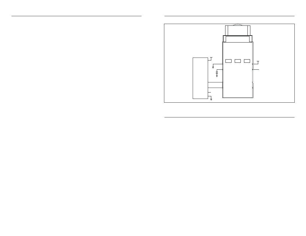
�TYPICAL� APPLICATIONS�
�Figure� 4� shows� a� typical� application� for� the� module.�
�(CPU)� to� determine� a� position� fix� (which� takes� about� 160mS).� Once� the� fix� is�
�obtained,� the� receiver� goes� into� a� low� power� standby� state.� After� a� user-defined�
�10�
�GND�
�GND�
�9�
�period� of� time,� the� receiver� wakes� up� to� track� the� satellites� for� a� user-defined�
�period� of� time,� updates� its� position� using� the� CPU� only,� and� then� resumes� stand-�
�by.� The� initial� acquisition� time� is� variable,� depending� on� whether� it� is� a� cold� start�
�or� assisted,� but� a� maximum� acquisition� time� is� definable.� This� cycling� of� power�
�VCC�
�is� ideal� for� battery-powered� applications� since� it� significantly� reduces� the� amount�
�of� power� consumed� by� the� receiver� while� still� providing� similar� performance� to�
�the� full� power� mode.�
�VCC�
�GND�
�1�
�2�
�GND�
�VBACKUP�
�VCC�
�EN�
�8�
�7�
�VCC�
�ENABLE�
�In� normal� conditions,� this� mode� provides� a� fixed� power� savings,� but� under� poor�
�signal� conditions,� the� receiver� returns� to� full� power� to� improve� performance.� The�
�receiver� sorts� the� satellites� according� to� signal� strength� and� if� the� fourth� satellite�
�is� below� 26dB-Hz,� then� the� receiver� switches� to� full� power.� Once� the� fourth�
�μ� P�
�RX�
�TX�
�GND�
�3�
�4�
�TX�
�RX�
�NC�
�LED�
�6�
�5�
�satellite� is� above� 3� 0dB-Hz,� the� receiver� returns� to� Adaptive� Trickle� Power� mode.�
�ENABLE�
�ENABLE�
�For� optimum� performance,� SiRF� recommends� cycle� times� of� 3� 00mS� track� to� 1S�
�interval� or� 400mS� track� to� 2S� interval.� CPU� time� is� about� 160mS� to� compute� the�
�navigation� solution� and� empty� the� UART.� There� are� some� situations� in� which� the�
�receiver� stays� in� full� power� mode.� These� are:� to� collect� periodic� ephemeris� data,�
�to� collect� periodic� ionospheric� data,� to� perform� RTC� convergence,� and� to�
�improve� the� navigation� result.� Depending� on� states� of� the� power� management,�
�the� receiver� will� be� in� one� of� three� system� states:�
�Full� Power� State�
�All� RF� and� baseband� circuitry� are� fully� powered.� There� is� a� difference� in� power�
�consumption� during� acquisition� mode� and� tracking� mode.� Acquisition� requires�
�more� processing,� so� it� consumes� more� power.� This� is� the� initial� state� of� the�
�receiver� and� it� stays� in� this� state� until� a� reliable� position� solution� is� achieved.�
�CPU� Only� State�
�This� state� is� entered� when� the� satellite� measurements� have� been� collected� but�
�the� navigation� solution� still� needs� to� be� computed.� The� RF� and� DSP� processing�
�are� no� longer� needed� and� can� be� turned� off.�
�Stand-By� State�
�In� this� state,� the� RF� section� is� completely� powered� off� and� the� clock� to� the�
�baseband� is� stopped.� About� 1mA� of� current� is� drawn� in� this� state� for� the� internal�
�core� regulator,� RTC� and� battery-backed� RAM.� The� receiver� enters� this� state�
�when� a� position� fix� has� been� computed� and� reported.�
�Page� 6�
�GND�
�GND�
�Figure� 3� :� SR� Series� Module� Typical� Application�
�SLOW� START� TIME�
�The� most� critical� factors� in� start� time� are� current� ephemeris� data,� signal� strength,�
�and� sky� view.� The� ephemeris� data� describes� the� path� of� each� satellite� as� they�
�orbit� the� earth.� This� is� used� to� calculate� the� position� of� a� satellite� at� a� particular�
�time.� This� data� is� only� usable� for� a� short� period� of� time,� so� if� it� has� been� more�
�than� a� few� hours� since� the� last� fix� or� if� the� location� has� significantly� changed� (a�
�few� hundred� miles),� then� the� receiver� may� need� to� wait� for� a� new� ephemeris�
�transmission� before� a� position� can� be� calculated.� The� GPS� satellites� transmit�
�the� ephemeris� data� every� 3� 0� seconds.� Transmissions� with� a� low� signal� strength�
�may� not� be� received� correctly� or� be� corrupted� by� ambient� noise.� The� view� of� the�
�sky� is� important� because� the� more� satellites� the� receiver� can� see,� the� faster� the�
�fix� and� the� more� accurate� the� position� will� be� when� the� fix� is� obtained.�
�If� the� receiver� is� in� a� very� poor� location,� such� as� inside� a� building,� urban� canyon,�
�or� dense� foliage,� then� the� time� to� first� fix� can� be� slowed.� In� very� poor� locations�
�with� poor� signal� strength� and� a� limited� view� of� the� sky� with� outdated� ephemeris�
�data,� this� could� be� on� the� order� of� several� minutes.� In� the� worst� cases,� the�
�receiver� may� need� to� receive� almanac� data,� which� describes� the� health� and�
�course� data� for� every� satellite� in� the� constellation.� This� data� is� transmitted� every�
�15� minutes.� If� a� lock� is� taking� a� long� time,� try� to� find� a� location� with� a� better� view�
�of� the� sky� and� fewer� obstructions.� Once� locked,� it� is� easier� for� the� receiver� to�
�maintain� the� position� fix.�
�Page� 7�
�发布紧急采购,3分钟左右您将得到回复。
相关PDF资料
RZE002P02TL
MOSFET P-CH 20V 200MA EMT3
RZF020P01TL
MOSFET P-CH 12V 2A TUMT3
RZF030P01TL
MOSFET P-CH 12V 3A TUMT3
RZM002P02T2L
MOSFET P-CH 20V 0.2A UMT6
RZQ045P01TR
MOSFET P-CH 12V 4.5A TSMT6
RZQ050P01TR
MOSFET P-CH 12V 5A TSMT6
RZR020P01TL
MOSFET P-CH 12V 2A TSMT3
RZR040P01TL
MOSFET P-CH 12V 4A TSMT3
相关代理商/技术参数
RXM-UHF
制造商:RADIOMETRIX 制造商全称:RADIOMETRIX 功能描述:UHF Radio Telemetry Receiver Module
RXP0005
制造商:Panasonic Industrial Company 功能描述:ARM
RXP0014
制造商:Panasonic Industrial Company 功能描述:PULLEY
RXP0015
制造商:Panasonic Industrial Company 功能描述:ROLLER
RXP0016
制造商:Panasonic Industrial Company 功能描述:ROLLER
RXP0016-4
制造商:Panasonic Industrial Company 功能描述:ROLLER
RXP0017
制造商:Panasonic Industrial Company 功能描述:ROLLER
RXP0017-3
制造商:Panasonic Industrial Company 功能描述:ROLLER